mirror of
https://github.com/jhbruhn/butns.git
synced 2025-07-01 17:08:49 +00:00
4.8 KiB
4.8 KiB
Overview
small grid 64 clone heavily based on previous work by hugelton/btns.
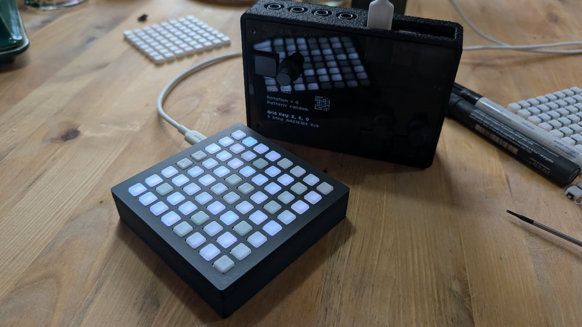
Uses a Rasperry Pi Pico Microcontroller, NeoPixel RGB LEDs (SK6812), cheap buttons and a 3d-printed case and button-overlay. Includes hardware and firmware support for an optional tilt-sensor.
Building
It is highly recommended to order the PCB assembled from JLCPCB. That assembly will include everything other than the parts in the BOM.
BOM
| Part | Quantity | Source | Required |
|---|---|---|---|
| PCB with components | 1 | JLCPCB, ordered with Gerber and Assembly files from latest release. Gerber: butns-JLCPCB.zip, BOM: butns_bom_jlc.csv, CPL: butns_cpl_jlc.csv. |
yes |
| Raspberry Pi Pico | 1 | Original Raspberry Pi Pico, or USB-C Variant | yes |
| M2.5x6 Button Head Screws | 5 | M2.5x6 | yes |
| Case | 1 | 3d-printed (FDM). case.stl contains the top and bottom half. In the image, it is printed in black PLA, 0.2mm layerheight. |
yes |
| Button Matrix | 1 | 3d-printed (FDM). Print buttons.stl with white PLA and 0.12mm layerheight and no infill, 2 wall lines, concentric top infill. These should guide the LEDs light well. Optional: Add buttons-black-blockers.stl while importing as a multi-material print and print those in black to block light from neighboring buttons |
yes (black blockers optional) |
| Button TPU Case Inlay | 1 | 3d-printed (FDM). Print with TPU, perhaps in black. Will help against rattling of the buttons in the case. | no |
| SMD 2.54" Pin Header 1x8 Type A | 1 | 1x8 Type A | no, for tilt |
| MPU6050 module | 1 | MPU6050 Module | no, for tilt |
Assembly
Flash microcontroller with firmware.uf2. Solder MCU and Pin-Header to PCB. Screw everything into the case. Done!
Hint: The cases Top half has one specific orientation where it fits nicely: The top-screw-posts of the top-half with the larger cutoaways go to the side opposite of the USB Connector.